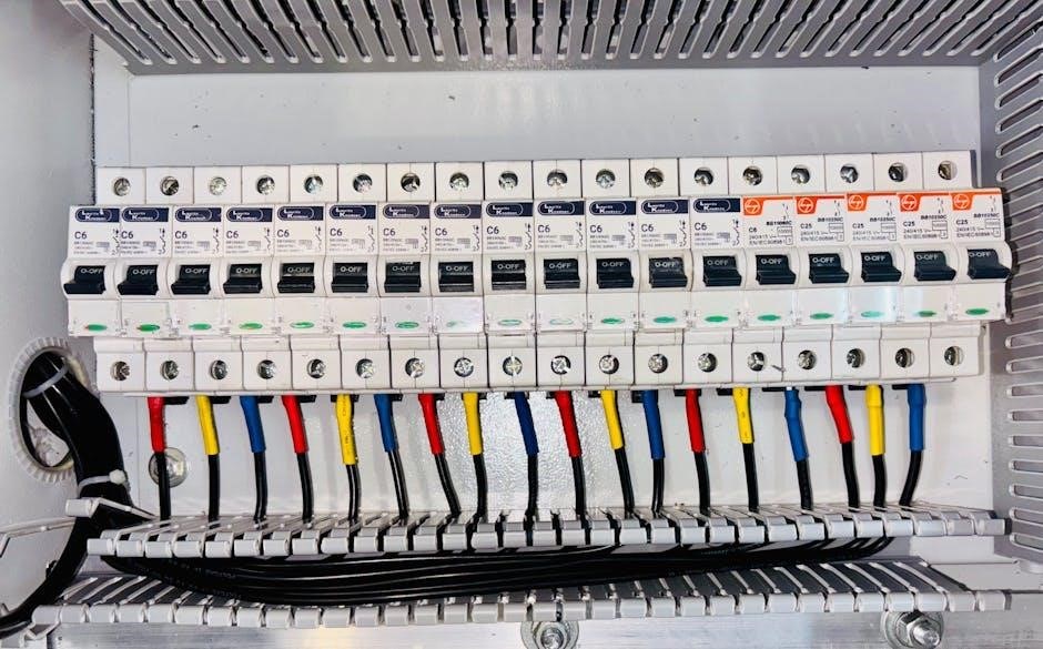
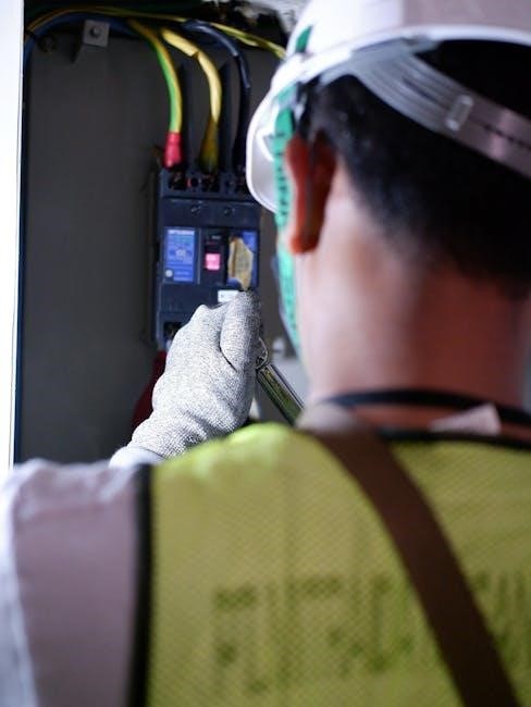
A 3-way switch enables control of a light fixture from two different locations. It’s commonly used in hallways‚ staircases‚ or large rooms for convenient lighting control.
1.1. What is a 3 Way Switch?
A 3-way switch is an electrical device designed to control a light fixture from two different locations. It features three terminals: one common and two travelers. This setup allows seamless operation of a single light source from multiple points‚ enhancing convenience in spaces like hallways or staircases. Unlike a standard switch‚ the 3-way switch enables dual control‚ making it a versatile solution for modern lighting systems.
1.2. Purpose and Applications
The primary purpose of a 3-way switch is to provide dual control over a single light fixture. Common applications include installation in hallways‚ staircases‚ and large rooms where multiple control points are essential. This setup enhances convenience‚ allowing users to operate lighting from two locations. It’s also ideal for energy efficiency‚ as it minimizes the need for additional fixtures‚ ensuring optimal lighting control without extra power consumption.

Key Components of a 3 Way Switch System
A 3-way switch system includes two 3-way switches‚ a light fixture‚ and specialized wiring. It allows dual control over a single light from two locations.
2.1. Switches and Their Types
In a 3-way switch system‚ two three-way switches are used to control a light from two locations. These switches have three terminals: common‚ traveler 1‚ and traveler 2. Unlike standard switches‚ they don’t have an “on/off” position but instead direct the electrical current. Types include toggle switches‚ paddle switches‚ and smart switches for modern automation. Each type requires precise wiring to ensure proper functionality and safe operation.
2.2. Wiring and Connections
In a 3-way switch setup‚ wiring involves connecting the common‚ traveler‚ and ground wires. The common wire connects to the light fixture‚ while the traveler wires link the two switches‚ allowing the current to pass through. Proper grounding ensures safety. Using a wiring diagram helps visualize these connections‚ preventing errors. Always follow local electrical codes and use the correct wire gauges for reliable performance and safety.
2.3. Power Sources and Loads
The power source in a 3-way switch system is typically connected to one of the switches. The load‚ such as a light fixture‚ is wired between the switches. Ensuring the power supply is correctly routed prevents short circuits. Always verify that the load is properly connected to maintain functionality. Using a wiring diagram helps identify where the power and load wires should be attached for safe and efficient operation.

Understanding 3 Way Switch Wiring Diagrams
3-way switch wiring diagrams visually represent connections and components. They illustrate how switches‚ lights‚ and power sources interact‚ simplifying installation and troubleshooting. Understanding these diagrams is crucial for safe setup.
3.1. Reading the Diagram
Reading a 3-way switch wiring diagram requires identifying components like switches‚ lights‚ and wires. Symbols denote power sources‚ loads‚ and connections. Lines represent wires‚ with colors indicating roles. Understanding these elements ensures proper installation. Diagrams also show switch positions and how they affect the circuit. This visual guide simplifies complex wiring scenarios‚ making it easier to troubleshoot and connect components correctly for reliable functionality. Always refer to the diagram for precise connections and safety.
3.2. Common Configurations
Common 3-way switch configurations include power-through-switch and power-through-light setups. In the first‚ power enters one switch‚ then travels to the light and the second switch. In the second‚ power goes directly to the light‚ with switches controlling it. These configurations ensure lights can be operated from two locations. Diagrams often show these setups‚ helping electricians and DIYers understand how to wire switches for reliable functionality and safe operation.
3;3. Symbols and Notations
Wiring diagrams use specific symbols to represent components. A 3-way switch is shown as two connected boxes with a common terminal; The light fixture is depicted as a circle or rectangle with a zigzag line. Power sources are marked with a circle or “HOT” label. Traveler wires are shown as lines connecting switches‚ while ground wires are indicated by a curved or diagonal line. Understanding these notations is key to interpreting diagrams accurately.

Step-by-Step Installation Guide
Begin by turning off the power supply. Use a voltage tester to ensure safety. Identify and label all wires using a wiring diagram as a guide. Prepare the switches and connections carefully‚ ensuring traveler wires are correctly linked between switches. Connect the common wire to the light fixture. Double-check all connections and test the system to verify proper functionality before finalizing the installation.
4.1. Planning the Installation
Before starting‚ assess the location and determine the best route for wiring. Identify the power source and light fixture placement. Use a wiring diagram to map connections. Ensure all materials‚ such as switches‚ wires‚ and connectors‚ are available. Measure and cut wires to appropriate lengths. Plan for traveler wires between switches and verify local electrical codes. Proper planning ensures a safe and efficient installation process‚ avoiding costly mistakes later.
4.2. Preparing the Wiring
Carefully prepare the wiring by stripping insulation from the ends of the cables. Identify the common‚ traveler‚ and ground wires. Use a wiring diagram to distinguish each wire’s purpose. Ensure all connections are clean and secure. Properly label wires to maintain consistency during installation. This step is crucial for ensuring the circuit functions correctly and safely. Always follow safety guidelines to prevent electrical hazards.
4.3. Connecting the Switches
Follow the wiring diagram to connect the switches. Identify the common‚ traveler‚ and ground wires. Connect the traveler wires between the switches to enable the circuit to function. Secure all connections tightly to prevent electrical hazards. Ensure the ground wire is properly attached for safety. Double-check the wiring to confirm it matches the diagram. Proper connections ensure reliable and safe operation.

Troubleshooting Common Issues
Identify faults like flickering lights or switches not working. Check connections for looseness and ensure wires match the wiring diagram. Test the system to confirm functionality.
5.1. Identifying Faults
Common issues include lights not turning on‚ flickering‚ or switches failing to control the fixture. Check for loose connections‚ incorrect wiring‚ or damaged wires. Verify that the wiring matches the 3-way switch diagram. Ensure power is off before inspecting. Test each switch to confirm functionality. If issues persist‚ consult the wiring diagram or seek professional assistance to resolve the problem effectively.
5.2. Repairing Connections
Begin by turning off the power supply. Inspect all wires and connections for damage or looseness. Tighten any loose screws and replace damaged wires. Ensure the wiring matches the 3-way switch diagram. Use a multimeter to verify continuity and proper connections. Reassemble the switches and test the system to confirm the repairs. If issues remain‚ consult the wiring diagram or consider professional help for further assistance.
5.3. Testing the System
After repairing connections‚ turn the power back on and test the system. Use a multimeter to verify voltage and continuity. Check all switch positions to ensure proper functionality; Toggle both switches to confirm the light turns on and off correctly. If issues persist‚ review the wiring diagram and connections. Verify that all wires are securely attached and that the circuit operates as intended before finalizing the repair.
Advanced Configurations and Variations
Explore advanced setups‚ including adding outlets‚ integrating dimmers‚ and controlling multiple fixtures. These configurations offer enhanced functionality and customization for complex lighting systems‚ requiring precise planning and expertise.
6.1. Adding Outlets
Integrating outlets with a 3-way switch system allows for additional power sources. This setup is ideal for rooms needing multiple electrical connections. Ensure the outlet is wired correctly‚ maintaining proper grounding. Use a 20-amp circuit if high-power devices are connected. Always follow local electrical codes and consult diagrams for accurate installation. This enhances functionality while preserving safety and efficiency in your space.
6.2. Integrating Dimmers
Integrating dimmers into a 3-way switch system allows for precise light control. Ensure the dimmer is compatible with your switch setup and the type of light bulbs used. Connect the dimmer in place of one of the 3-way switches‚ following the manufacturer’s wiring diagram. Always verify the load rating and compatibility with LED or smart bulbs to avoid malfunctions. This enhances lighting flexibility and energy efficiency in your space.
6.3. Multiple Light Fixtures
Controlling multiple light fixtures with a 3-way switch system is straightforward. Connect the common wire to the first fixture‚ and use traveler wires to link subsequent fixtures. Ensure all fixtures are wired in parallel to maintain proper voltage. Verify connections to avoid short circuits or malfunctions. This setup allows seamless control of all lights from two or more locations‚ enhancing convenience and energy efficiency in larger spaces or multi-fixture setups.

Safety Guidelines and Precautions
Always disconnect power before starting work. Use insulated tools and ensure all connections are secure. Follow local electrical codes to prevent hazards and ensure compliance.
7.1. Electrical Safety Tips
Always turn off the power supply at the breaker box before starting any wiring project. Verify the absence of voltage using a multimeter to ensure safety. Use insulated tools and wear protective gear to avoid electric shocks. Never touch wires with bare hands or while standing on a damp surface. Follow all local electrical codes and regulations strictly. Properly secure all connections to prevent loose wires‚ which can cause short circuits or fires. If unsure about any step‚ consult a licensed electrician to avoid potential hazards. Regularly inspect wiring for signs of wear or damage and address issues promptly to maintain a safe electrical system. Adhere to the manufacturer’s instructions for any devices or materials used in the project. Keep the work area well-lit and uncluttered to minimize accidents and ensure clear visibility while working. By prioritizing safety‚ you can complete the wiring project efficiently and without risking personal harm or property damage; Remember‚ electrical safety is paramount and should never be compromised for convenience or speed.
7.2. Avoiding Common Mistakes
When wiring a 3-way switch‚ common mistakes include incorrectly identifying the common wire and traveler wires‚ which can lead to improper functionality. Always double-check the wiring diagram to ensure correct connections. Mixing up the load and line wires is another frequent error‚ so verify the circuit layout before proceeding. Forgetting to turn off the power supply is dangerous and can result in electric shock. Additionally‚ using the wrong gauge of wire or improperly securing connections can cause malfunction or fire hazards. To avoid these issues‚ carefully follow the wiring diagram and test each connection with a multimeter before restoring power. Proper planning and attention to detail are essential to ensure a safe and functional installation. By addressing these potential pitfalls‚ you can achieve a reliable and efficient 3-way switch system that operates as intended without unnecessary risks or complications.
7.3. Compliance with Local Codes
Ensure your 3-way switch wiring complies with local electrical codes and regulations. Hire a licensed electrician if unsure‚ as non-compliance can lead to safety hazards or legal issues. Always follow the National Electric Code (NEC) guidelines for wiring practices. Obtain necessary permits and inspections to verify compliance. Proper wire sizing‚ grounding‚ and circuit protection are critical. Adhere to local amendments and standards for residential wiring‚ such as those outlined in the International Residential Code (IRC). Compliance ensures safety‚ avoids fines‚ and guarantees your system meets legal requirements.

Additional Resources and Tools
For further guidance‚ explore online tutorials‚ wiring diagrams‚ and PDF guides. Essential tools include multimeters‚ wire strippers‚ and voltage testers to ensure safe and accurate installations.
8.1. Recommended Tools
Essential tools for 3-way switch wiring include a multimeter for testing circuits‚ wire strippers for preparing wires‚ and a voltage tester to ensure safety. Pliers and screwdrivers are also necessary for secure connections. Additionally‚ a wire connector kit and a circuit tester can be beneficial for troubleshooting and ensuring all connections are properly made. These tools help streamline the installation process and minimize errors.
8.2. Further Reading
For in-depth understanding‚ explore wiring diagrams and guides available online. Resources like cbyge.com/switch offer detailed instructions for installing and troubleshooting 3-way switches. Additionally‚ PDF manuals provide comprehensive step-by-step wiring procedures‚ ensuring safe and efficient installations. These materials cover various configurations‚ including power-through-switch setups and multiple light fixtures‚ making them invaluable for both beginners and experienced electricians looking to refine their skills.
8.3. Online Tutorials
Online tutorials provide step-by-step guidance for wiring 3-way switches. Websites like cbyge.com/switch offer detailed videos and PDF guides. These resources cover troubleshooting‚ installation‚ and advanced configurations. Tutorials often include visual diagrams‚ making complex wiring processes easier to understand. They cater to both novices and experienced individuals‚ ensuring a smooth learning curve for mastering 3-way switch wiring and related electrical projects.
Verify the setup‚ ensure proper functionality‚ and schedule regular maintenance. A well-installed 3-way switch system enhances convenience and safety in controlling lighting fixtures.
9.1. Verifying the Setup
After installation‚ verify the 3-way switch setup by testing all possible configurations. Ensure both switches control the light fixture correctly and check for any short circuits or faulty connections. Use a voltage tester to confirm power is present only when switches are in the correct positions. Review the wiring diagram to ensure all connections match the intended design. Proper verification ensures safety‚ reliability‚ and optimal performance of the lighting system.
9.2. Ensuring Proper Functionality
Test all switch configurations to confirm the light operates as intended. Check for consistent power delivery and smooth transitions between states. Verify that both switches control the fixture correctly and no unintended behaviors occur. Ensure all connections are secure and meet the wiring diagram specifications. Proper functionality guarantees reliable operation‚ energy efficiency‚ and safety‚ making the system user-friendly and hazard-free.
9.3. Future Maintenance
Regularly inspect the wiring and connections to ensure long-term reliability. Check for loose wires‚ corrosion‚ or damage that may affect performance. Refer to the 3-way switch wiring diagram to verify all connections remain accurate. Clean or replace components as needed to maintain optimal functionality. Schedule periodic testing of the system to catch potential issues early. Always follow safety guidelines and consult a professional if unsure. Proper maintenance ensures the system continues to function safely and efficiently.

